Solar + EV Charge Station + Energy Storage
3-in-1 Solution
PV + ESS + EV Charger solution
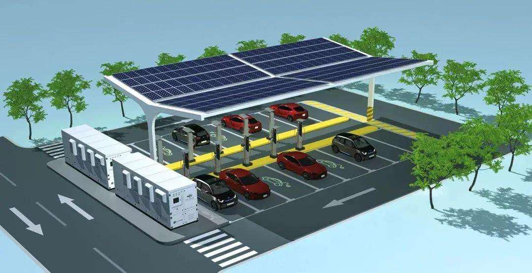
The scheme of this project utilizes the existing roof and parking lot of 4s store in US to set up roof and carport PV, and constructs distributed PV power station to provide electricity for all loads and charging service for electric vehicles, and at the same time, utilizes the system to solar self-consumption, and provides peak shaving for the key loads of the building as well as the guarantee for the uninterrupted power supply through the system. The charging station is utilized to open charging services to the society, increasing production and efficiency for the project and creating greater income.
The roof and carport PV use AC busbar access to provide power directly to the target loads. This project realizes the typical application of the integration of photovoltaic, energy storage and charging station.
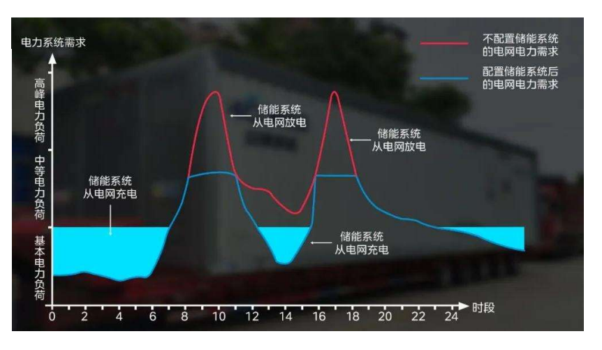
The integration of PV+ ESS + EV Charger uses the energy storage system to improve the utilization rate of PV consumption, and at the same time stores the energy during the low price of electricity, charges during the peak period through the storage power station and the grid together for the charging station power supply, not only to achieve the peak shaving to fill in the valley, but also to save the distribution of additional capacity costs, which can effectively solve the new energy power unstable generation and other issues.
The system consists of:
- Distributed photovoltaic power generation system: including photovoltaic square array and photovoltaic on-grid inverter;
- Energy storage system: including energy storage battery pack and energy storage inverter PCS;
- New energy charging system: including DC charging stack and charging terminals;
- Control system: including EMS energy management system;
- Load: new energy vehicle charging and office electricity.
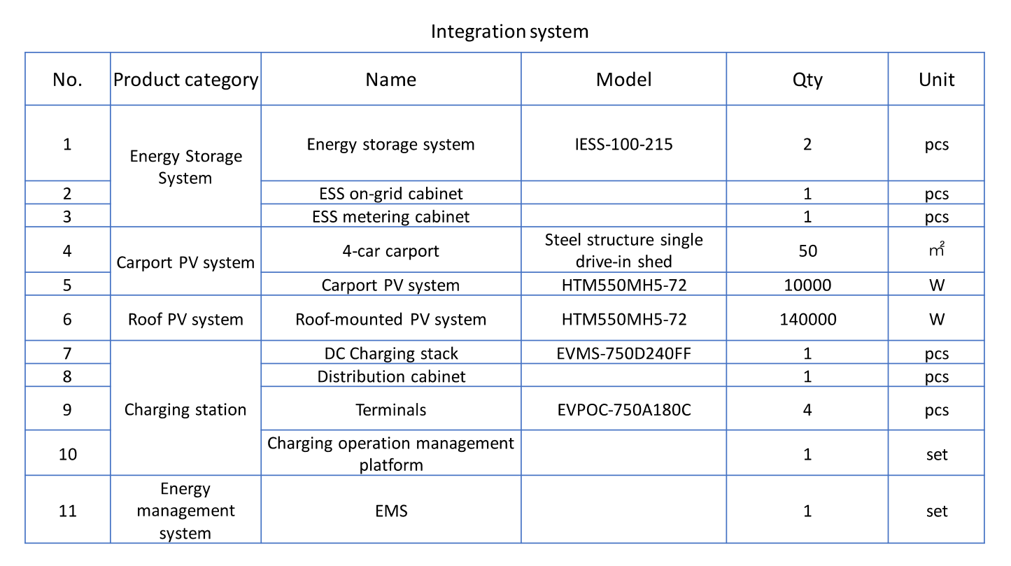
Project construction scale:
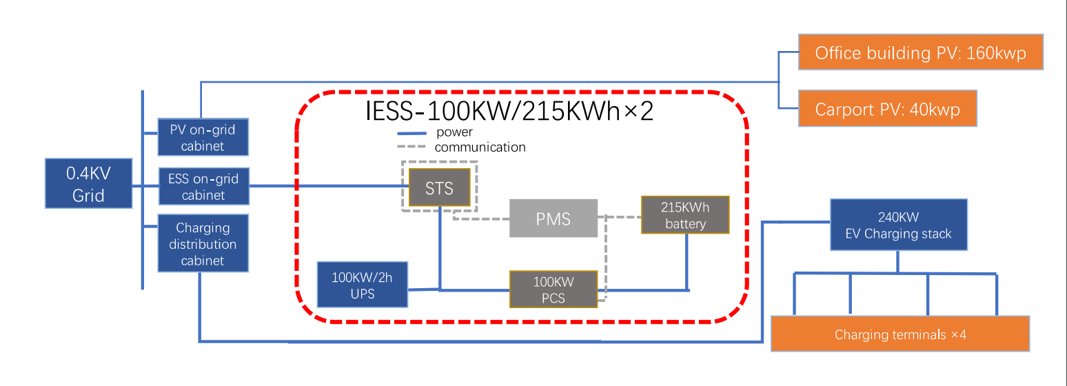
- Carport PV: designed installed capacity 40kwp;
- Office building roof PV: designed installed capacity 160kwp;
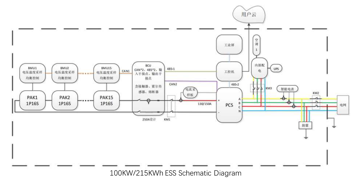
- Energy storage system: designed installed capacity 100KW/215KWh;
- Charging station: designed installed capacity: 240KW.
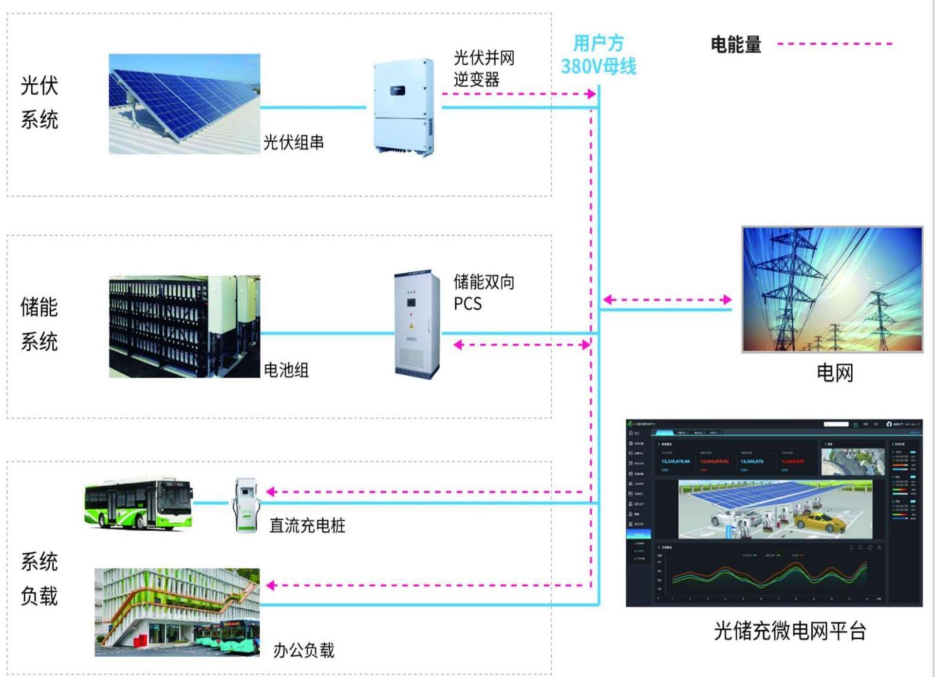
The system load can be powered by three sources: the PV system, the energy storage system, and the grid system.
Priority level:
1. Photovoltaic system > 2. Energy storage system > 3. Grid system.
The whole system is controlled by the EMS control system and intelligently monitored by the PV+ ESS+ EV Charger microgrid platform.
The main features of the integration system:
- Photovoltaic power generation self-generation and self-consumption;
- Grid peak shaving and valley filling, reducing the cost of electricity;
- Intelligent charging, providing charging guarantee for the EV;
- When grid blackout, provide short-term power supply protection;
- Sustainable profitability.
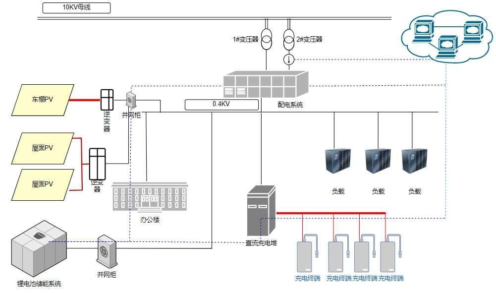
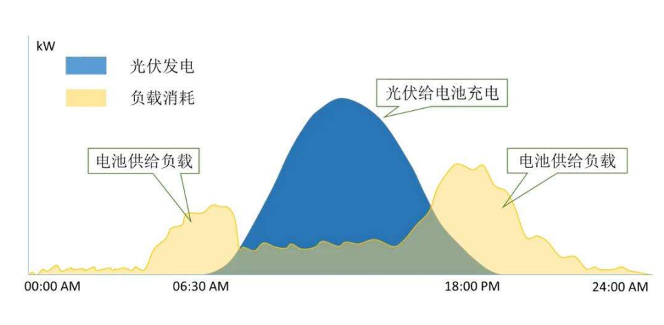
Load Power Logic
The office area power consumption and charging station prioritizes the use of PV green power, followed by the use of energy storage, and finally the use of grid. PV, energy storage and charging station and the park power grid use AC access to jointly realize the typical application of PV, energy storage and charging integration.
PV Electrics
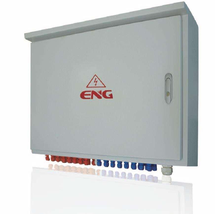
DC Combiner Box
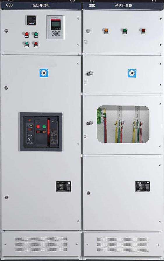
Low-voltage on-grid cabinet
l00KW PV inverter
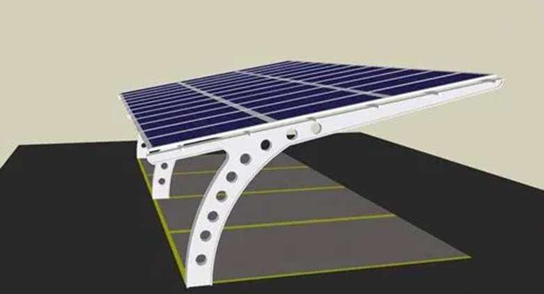
Carport PV
40KWp carport photovoltaic, 13 parking spaces single column carport, the main material is made of steel structure, with the advantages of low carbon, energy saving, green environmental protection, reusable and so on.
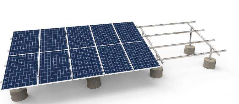
Roof-mounted PV
160KWp roof PV, laying an area of 800 square meters, using flat laying method for installation, simple installation, can install more photovoltaic panels, power generation efficiency is relatively higher.
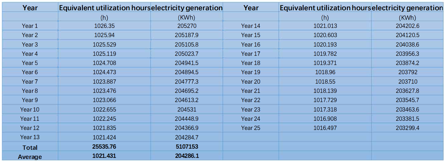
PV Power Generation
The total installed capacity of the project is 200 KWp, and the total power generation capacity for 25 years is 5.107 million KWh, with an average annual generation capacity of 204,200 KWh. the average equivalent utilization hours for 25 years is 1,021.43 h. The project is expected to be completed by the end of this year.
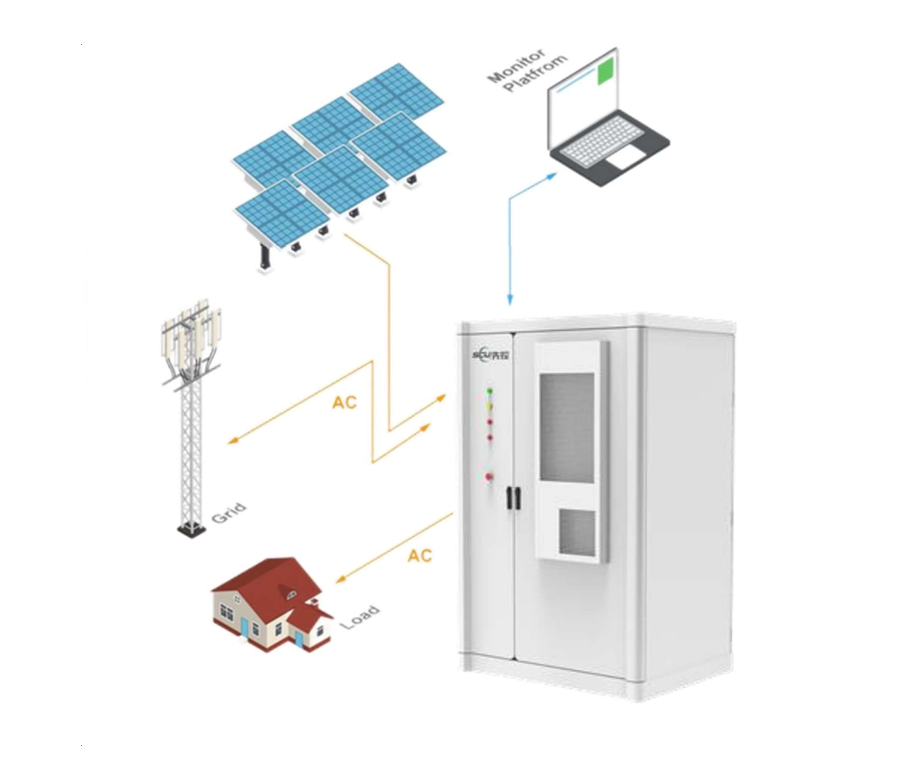
Energy Storage System
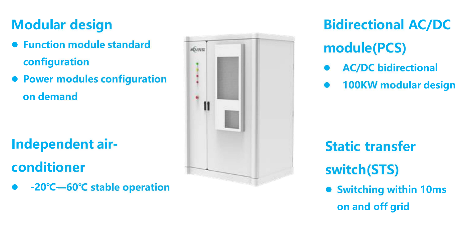
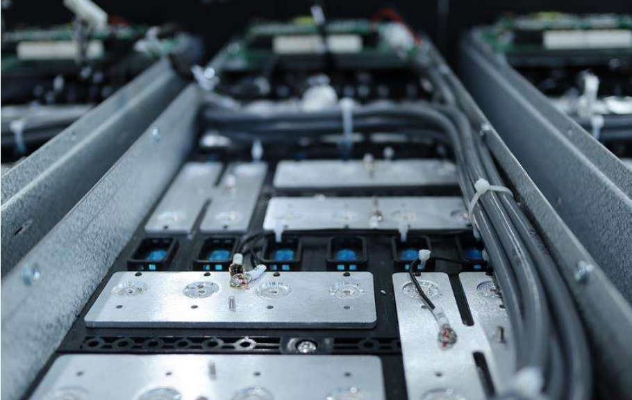
IESS (Integrated Energy Storage System) energy storage integrated power system, it integrates long-life lithium battery, battery management system BMS, high-performance bidirectional energy storage converter module (PCM100), active safety system, thermal management system, and energy management system into a single standardized outdoor cabinet to form an integrated plug-and-play intelligent, modular power supply equipment.
Each cabinet is an independent unit, capable of energy storage and AC/DC power change, and equipped with air-conditioner temperature control system and fire protection system, which can run safety, stably, and reliably for a long time. Through parallel connection on the AC side, the capacity can be flexibly expanded to achieve flexible expansion of energy storage power station capacity.
The organic combination of photovoltaic power generation system and energy storage system can realize the transformation from passive energy saving to active energy output, and through the control strategy of PMS, the power grid and the new energy and energy storage batteries can realize the mutual integration and energy complementation, which can significantly reduce the cost of electricity consumption of customers.
ESS
The energy storage system can not only make full use of solar energy resources to realize self-generation and self-consumption of energy, but also meet the needs of customers for various applications of new energy. The working mode of the system is divided into grid-connected charging mode, grid-connected discharging mode and static mode.
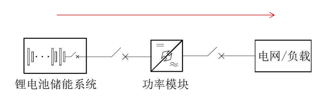
On-Grid charging mode:
When the utility and battery of the PCS system are connected normally, the PCS system can work in the grid-connected charging mode according to the user's settings, at this time the system will convert the AC utility power into DC power to charge the energy storage battery.

Energy flow during on-grid charging mode of PCS system
On-grid discharge mode
When the utility and battery access of the PCS system are normal, the PCS system can work in the grid-connected discharge mode according to the user settings, at which time the system converts the DC power from the energy storage battery into AC power to feed back into the grid.
Quiescent mode:
When the utility and battery access of the PCS system are normal, the PCS system can work in the grid-connected quiescent mode according to the user setting, at this time the system will isolate the energy storage battery from the grid, and no charging and discharging operations will be carried out.
Battery Safety Solution
Prevention, protection, elimination, three-level safety management
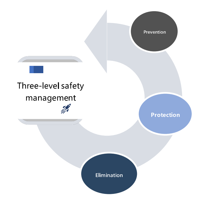
Prevention
- Cell selection
- Pack form
- Battery string connection mode
Protection
- BMS Battery management system
- Monitoring unit system detection and early warning
- Electrical hardware protection
Elimination
- Built-in fire control measures and fire control linkage measures
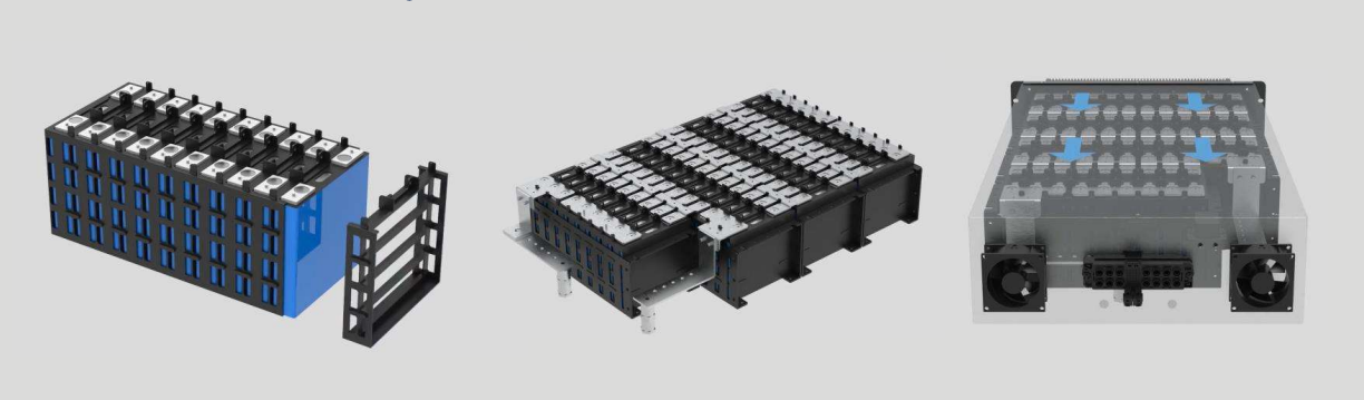
Prevention - Pack composition
Lithium battery system adopts rack structure, scientific structure and high mechanical strength. Modular design, easy installation, easy maintenance. The whole structure ensures the reliability and security of the system to the greatest extent.
Laser welding (button)
Laser welding connection, high strength, low internal resistance, compared with bolt fixing method more reliable. Bolts have the risk of screw loosening, which will cause damage to the corresponding cell and affect the operation of the whole system.
Structural Characterstics
Heat Dissipation Design
The design of reasonable and reliable heat dissipation channel, the use of intelligent air cooling technology, when the battery is running, the heat emitted by the battery can be exported to the module or system in time, improve the stability and reliability of the system.
Insulation Design
In addition to the PE blue insulating film of the cell itself, the plastic insulating bracket with high melting point and 2000V resistance is used to insulate and fix the cell, preventing touch and short circuit. It can maintain the insulation between cells to the maximum extent even when abnormal conditions occur, and improve the safety of the whole system.
Thermal isolation Design
Design >7mm spacing between cells to realize thermal isolation, avoid triggering thermal runaway cell adjacent cell temperature increase, reduce the risk of thermal runaway chain effect caused by heat conduction;
Safety design
The space above the pressure relief valve is reserved to prevent the explosion caused by excessive pressure in case of abnormal.
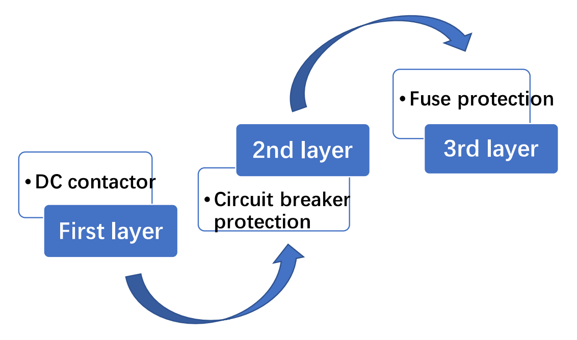
Protection : Electrical Hardware Protection
Level 1 protection: It is realized by DC contactor. When the battery management system recognizes the overcurrent phenomenon, the DC contactor will trip to ensure that the system is not harmed by current.
Level 2 protection: By the circuit breaker, when the DC contactor can not break due to the DC overcurrent arc, can realize further overcurrent protection and short circuit protection;
Level 3 protection:
By the fuse protection, when the circuit breaker also fails to disconnect the circuit, by the fuse to achieve the third level of protection, to ensure the safety of the battery system.
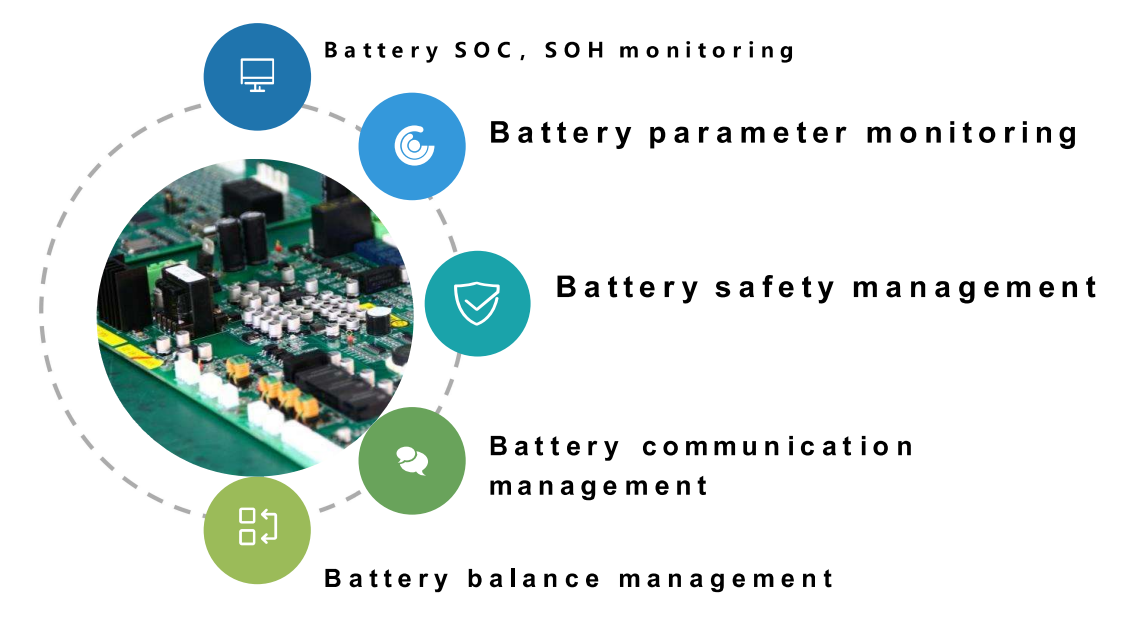
Protection - BMS System
The battery management system is one of the core components of the energy storage system. Excellent BMS can ensure the excellent performance of the single cell group in terms of safety, life and discharge ability, effectively protect the overcharge, overdischarge and overcurrent of the battery, and avoid the imbalance of the single cell and uneven temperature distribution caused by the battery in the case of long time and high rate charge and discharge. Ensure the safe, reliable and efficient operation of the whole system.
Energy transfer active equilibrium
The balancing accuracy is less than 2%, and the balancing capacity can reach 10% of the rated output; The capacity of a single cell does not affect the system capacity.
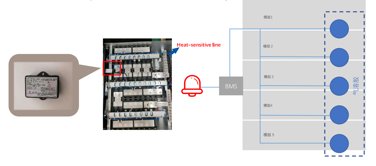
Elimination - fire protection measures
Compared with traditional fire control measures outside the system, the built-in aerosol mode can be used to intervene earlier and effectively reduce the spread of thermal runaway. At the same time, when the aerosol occurs, the BMS system will synchronize the linkage operation, forcibly disconnect the battery charge and discharge loop, trigger the fire alarm and fire response action, which can ensure that the battery fault is controlled in a minimum range.
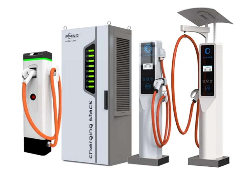
EV Charger
The charging system used in this project is a split charging system, which has the following features compared with the traditional one- piece charging system:
- More intelligent charging management than the traditional one-piece equipment;
- Stronger automated charging management capability at the field station level;
- More flexible charging space arrangement than traditional charging piles.
Large capacity: 240KW
Wide range: DC output voltage 50-1000VDC
Constant power voltage range: 300-1000VDC
Convenient storage: cantilever type / pulley type
Unique heat dissipation: Separate hot and cold air ducts
Multiple Outputs: Each charger can output multiple channels at the same time;
Intelligent distribution: Intelligent distribution of power according to vehicle BMS requirements to improve charging efficiency.
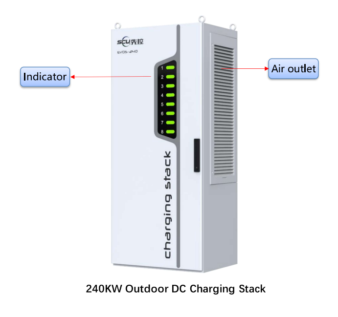
EVMS - 240
Power: 240KW
Power module: 8
Outlet: 4 channels
Output voltage: 50-750VDC
Each power: 0KW-60KW 0KW-120KW
Protection degree: IP54
Dimension W*D*H (mm): 800*750*1950
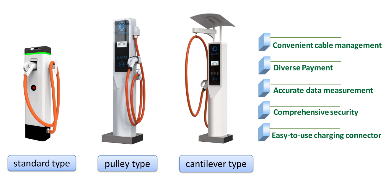
Types of DC Charging Terminals
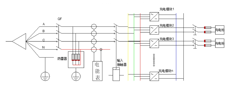
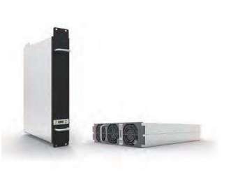
Power Module
Features:
- Wide input voltage range of 260V~530V, with lightning protection design;
- Module adopts digital control technology, pure digital control from input to output; adopts interleaved series resonance soft switching technology to make the power devices bear less stress;
- Input harmonics less than 3%, input power factor up to 0.99;
- Output DC ripple is small and has no effect on battery life;
- Safety protection functions such as over-voltage protection on the input side of the power supply, under-voltage alarm, over-current and short-circuit protection on the output side;
- Can be formed into a parallel redundant system with the function of plug-and-play replacement, so that the availability, reliability and maintainability of the system have been greatly improved.
EV Charger -Product Advantages

Less Investment
Compared with the traditional one-piece charging pile, it saves 30% of floor space, 40% of power investment and 40% of equipment investment.

Better Utilization and Efficiency
Increase equipment utilization rate, the general charging station equipment utilization rate is less than 10%, the utilization rate of the charging stack is more than 30%. Charging time is saved by 30%, module life is extended by 50%, and system efficiency is increased by 3%.

Better Load Balancing
The charging stack adopts dynamic load balance, which can adjust the output power according to the different needs of vehicles to achieve the best match with the load; and the charging stack system flexibly adjusts its own total power according to the available capacity of the utility power, which also achieves a better balance with the power grid.

More Flexible Charging Solutions
The output power adopts dynamic load balance, which can be set up in various working modes to realize the function of shaving peaks and filling valleys by equalizing charging, rotating charging and dynamic load balance according to the time period. The output power is dynamically adjusted according to the demand of new energy vehicles to match the best charging state. The service capacity of the station is stronger and can accommodate more new energy vehicles at the same time.

Broader Value Added
The 12-inch large screen display can play advertising messages. The DC operation unit adopts advertisability design, high-end premium advertising screen, and it is simple and fast to replace the advertisement pictures through external SD card, or remote refreshment, which has wide publicity space and value-added value.
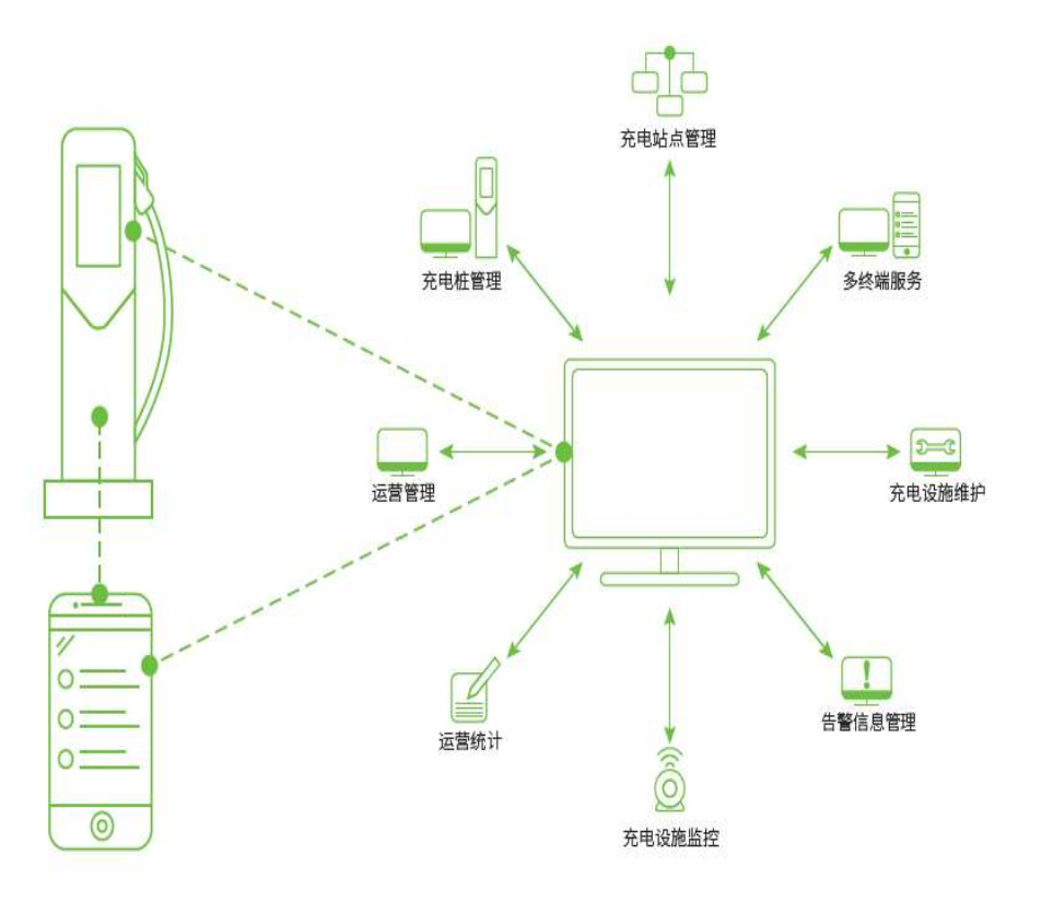
Charging Management Platform
The charging operation and management platform can not only access to power suppliers, charging pile operators and other charging facilities providers to achieve unified access to charging infrastructure. It can also access to vehicle enterprises, fleets and other charging facilities demand side so that the platform charging piles directly empowered to the vehicle enterprises, fleets and other different subjects; more access to the government regulatory authorities to achieve the city charging facilities hot and cold zone planning, to further optimize the adjustment of the distribution of urban charging infrastructure, to solve the related urban development and planning issues.
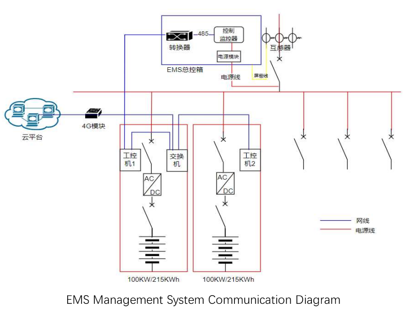
EMS
EMS provides integrated control and monitoring functions for the whole scheme, collects and analyzes the real-time data of various equipment in the ESS system, and monitors various key data parameters in real time.
It is composed of sever, user interface, controller, measuring unit, sensor and cloud platform.
According to its application type, it can realize the function of equipment information collection, control, data summary, chart analysis and so on, and form a set of scientific and energy-saving energy management scheme according to the electricity price, time period, battery BMS data, load rate and so on.
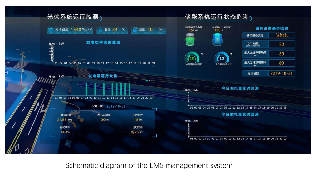
Main function of EMS
Power Station Monitoring
7 * 24 hours second-level real-time monitoring, equipment start/stop control; intelligent alarms, multiple notification methods.
Energy Storage Management
Energy demand management, power factor adjustment, energy storage system SOC display, charging and discharging times display, load monitoring, tariff optimization.
Energy Efficiency Management
Simultaneous and cyclic analysis; energy consumption tracking; fast discovery of large energy users and consumption increase points.
Equipment Management
Full life cycle management of equipment; electronic archives; APP mobile management.
Efficient Operation and Maintenance
Online and offline unified operation and maintenance; automatic tracking and recording of the whole operation and maintenance process.
Power Quality Optimization
Active power automatic control, reactive power control, three-phase imbalance adjustment, harmonic and other visualization control, intelligent alarm.
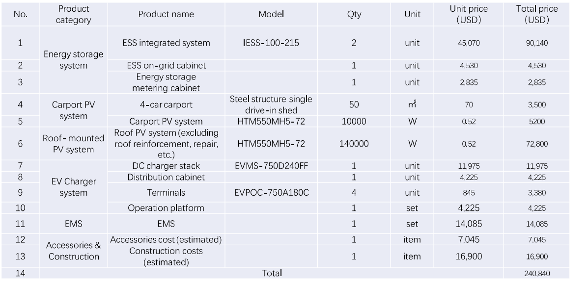
Estimates of Investments